

2 phases 1.8° hybrid stepper motor is the most popular in market and has the most extensive product coverage, as a result of a series of optimizations and improvements, its performance and value has been greatly improved.

A stepper motor is an electromechanical device it converts electrical power into mechanical power. Also it is a brushless, synchronous electric motor that can divide a full rotation into an expansive number of steps. The motor’s position can be controlled accurately without any feedback mechanism, as long as the motor is carefully sized to the application.

Shaft Options 、 Lead Wires & Cables、 Electrical Modifications、 Windings、 Accessories options、 Encoders、 Press Fit Pulley & Gear、 Brake、 IP Ratings、 ...

Stepper motors are widely used in all areas of production practice. Its largest application is in the manufacture of CNC machine tools. Because stepper motors do not require a/d conversion and can directly convert digital pulse signals into angular displacement, they are considered ideal actuating elements for CNC machine tools.


When motor applied in industrial robot, we should mainly pay attention to the following basic performance of motor: It can start, stop and run clockwise and anticlockwise continuously , and has good feedback.


Typical mechanic systems driven by the tractor or prime mover are being replaced by more sophisticated and efficient electromechanical systems which allow farmers to increase their production yields.


As the world becomes more industrialised and automated the need for efficient, accurate quality motions solutions is paramount
Stepper motor
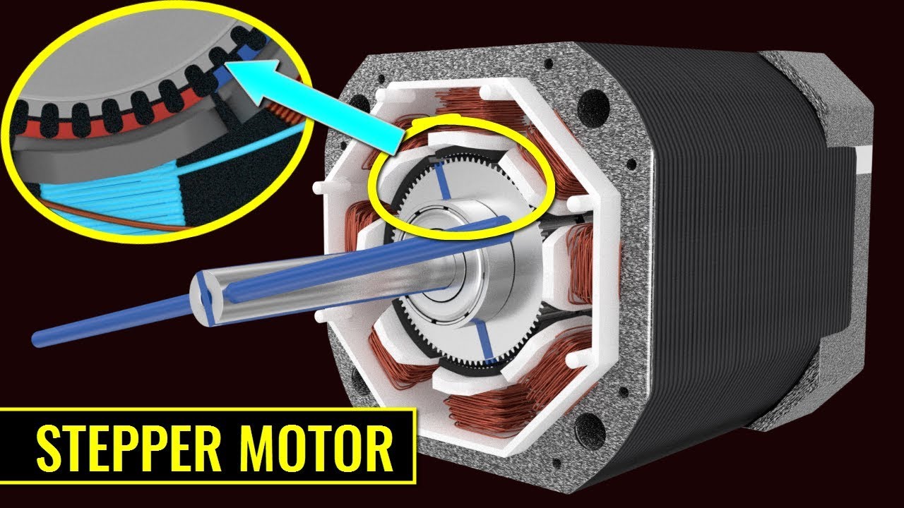
A stepper motor is an electromechanical device it converts electrical power into mechanical power. Also it is a brushless, synchronous electric motor that can divide a full rotation into an expansive number of steps. The motor’s position can be controlled accurately without any feedback mechanism, as long as the motor is carefully sized to the application. Stepper motors are similar to switched reluctance motors.
The stepper motor uses the theory of operation for magnets to make the motor shaft turn a precise distance when a pulse of electricity is provided. The stator has eight poles, and the rotor has six poles. The rotor will require 24 pulses of electricity to move the 24 steps to make one complete revolution. Another way to say this is that the rotor will move precisely 15° for each pulse of electricity that the motor receives.
Structure of Stepper Motor :
The figures below show two cross-sections of a 5-phase stepper motor. The stepper motor consists primarily of two parts: a stator and rotor. The rotor is made up of three components: rotor 1, rotor 2 and a permanent magnet. The rotor is magnetized in the axial direction so that, for example, if rotor 1 is polarized north, rotor 2 will be polarized south.
The stator has ten magnetic poles with small teeth, each pole being provided with a winding. Each winding is connected to the winding of the opposite pole so that both poles are magnetized in the same polarity when current is sent through the pair of windings. (Running a current through a given winding magnetizes the opposing pair of poles in the same polarity, i.e., north or south.)
The opposing pair of poles constitutes one phase. Since there are five phases, A through E, the motor is called a “5-phase stepper motor.”
There are 50 small teeth on the outer perimeter of each rotor, with the small teeth of rotor 1 and rotor 2 being mechanically offset from each other by half a tooth pitch.
Excitation: To send current through a motor winding
Magnetic pole: A projected part of the stator, magnetized by excitation
Small teeth: The teeth on the rotor and stator.
Principle of Operation
Following is an explanation of the relationship between the magnetized stator small teeth and rotor small teeth.
When Phase “A” is Excited
When phase A is excited, its poles are polarized south. This attracts the teeth of rotor 1, which are polarized north, while repelling the teeth of rotor 2, which are polarized south. Therefore, the forces on the entire unit in equilibrium hold the rotor stationary. At this time, the teeth of the phase B poles, which are not excited, are misaligned with the south-polarized teeth of rotor 2 so that they are offset 0.72˚. This summarizes the relationship between the stator teeth and rotor teeth with phase A excited.
When Phase “B” is Excited
When excitation switches from phase A to B, the phase B poles are polarized north, attracting the south polarity of rotor 2 and repelling the north polarity of rotor 1.
In other words, when excitation switches from phase A to B, the rotor rotates by 0.72˚. As excitation shifts from phase A, to phases B, C, D and E, then back around to phase A, the stepping motor rotates precisely in 0.72˚ steps. To rotate in reverse, reverse the excitation sequence to phase A, E, D, C, B, then back around to phase A.
High resolution of 0.72˚ is inherent in the mechanical offset between the stator and rotor, accounting for the achievement of precise positioning without the use of an encoder or other sensors. High stopping accuracy of }3 arc minutes (with no load) is obtained, since the only factors affecting stopping accuracy are variations in the machining precision of the stator and rotor, assembly precision and DC resistance of windings.
The driver performs the role of phase switching, and its timing is controlled by a pulse-signal input to the driver. The example above shows the excitation advancing one phase at a time, but in an actual stepper motor an effective use of the windings is by exciting four or five phases simultaneously.
Types of Stepper Motor:
There are three main types of stepper motors, they are:-
Permanent Magnet Stepper Motor Permanent magnet motors use a permanent magnet (PM) in the rotor and operate on the attraction or repulsion between the rotor PM and the stator electromagnets.
Variable Reluctance Stepper Motor: Variable reluctance (VR) motors have a plain iron rotor and operate based on the principle that minimum reluctance occurs with minimum gap, hence the rotor points are attracted toward the stator magnet poles.
Hybrid Synchronous Stepper Motor: Hybrid stepper motors are named because they use a combination of permanent magnet (PM) and variable reluctance (VR) techniques to achieve maximum power in a small package size.
Advantages of Stepper Motor:


+86 13775107620

Wujin High-Tech Zone, Changzhou, Jiangsu, China


